Configure Basic VLAN and Trunking on 2 Cisco Switches
When managing modern networks, VLANs (Virtual Local Area Networks) and trunking play a crucial role in segmenting traffic and allowing seamless communication between devices across switches. This article provides a detailed guide on how to configure VLANs and trunking on two Cisco switches based on the provided topology.
Topology Overview

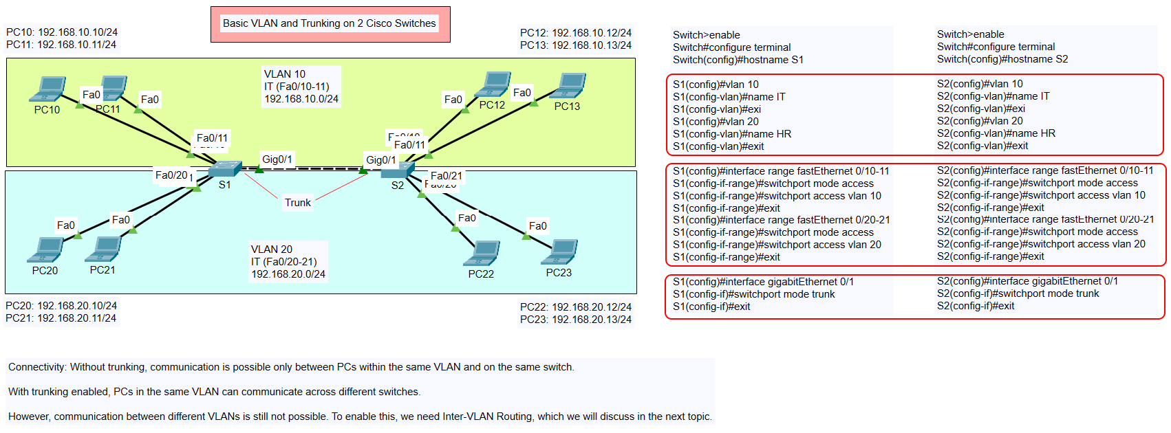
The network topology consists of:
- Two switches: S1 and S2.
- Four VLANs:
- VLAN 10 (IT department, 192.168.10.0/24).
- VLAN 20 (HR department, 192.168.20.0/24).
- PCs connected to respective VLANs:
- VLAN 10: PC10, PC11, PC12, PC13.
- VLAN 20: PC20, PC21, PC22, PC23.
- Trunk connection between the two switches via
GigabitEthernet0/1.
Connectivity Explanation
- Without Trunking: Communication is restricted to devices within the same VLAN on the same switch.
- With Trunking Enabled: Devices in the same VLAN can communicate across switches through the trunk link.
- Inter-VLAN Communication: Requires Inter-VLAN Routing, which is beyond the scope of this topic.
Other types of VLAN Configuration
- Configure Basic VLAN and Assign Port on a Cisco Switch
- Configure Basic VLAN and Trunking on 2 Cisco Switches
Steps to Configure VLAN and Trunking
Below are the detailed configuration steps for S1 and S2:
Step 1: Configure VLANs on Each Switch
VLANs need to be created on both switches to segment network traffic properly.
Commands for S1:
Switch>enable
Switch#configure terminal
Switch(config)#hostname S1

S1(config)#vlan 10
S1(config-vlan)#name IT
S1(config-vlan)#exit

S1(config)#vlan 20
S1(config-vlan)#name HR
S1(config-vlan)#exit
Commands for S2:
Switch>enable
Switch#configure terminal
Switch(config)#hostname S2

S2(config)#vlan 10
S2(config-vlan)#name IT
S2(config-vlan)#exit

S2(config)#vlan 20
S2(config-vlan)#name HR
S2(config-vlan)#exit
Step 2: Assign VLANs to Access Ports
Next, assign specific VLANs to the ports where the PCs are connected.
Commands for S1:
Assign VLAN 10 to ports FastEthernet0/10-11:
S1(config)#interface range fastEthernet 0/10-11
S1(config-if-range)#switchport mode access
S1(config-if-range)#switchport access vlan 10
S1(config-if-range)#exit
Assign VLAN 20 to ports FastEthernet0/20-21:
S1(config)#interface range fastEthernet 0/20-21
S1(config-if-range)#switchport mode access
S1(config-if-range)#switchport access vlan 20
S1(config-if-range)#exit
Commands for S2:
Assign VLAN 10 to ports FastEthernet0/10-11:
S2(config)#interface range fastEthernet 0/10-11
S2(config-if-range)#switchport mode access
S2(config-if-range)#switchport access vlan 10
S2(config-if-range)#exit
Assign VLAN 20 to ports FastEthernet0/20-21:
S2(config)#interface range fastEthernet 0/20-21
S2(config-if-range)#switchport mode access
S2(config-if-range)#switchport access vlan 20
S2(config-if-range)#exit
Step 3: Configure the Trunk Port
To enable communication between the switches for the same VLAN, configure the trunk link on GigabitEthernet0/1 on both switches.
Commands for S1:
S1(config)#interface gigabitEthernet 0/1
S1(config-if)#switchport mode trunk
S1(config-if)#exit
Commands for S2:
S2(config)#interface gigabitEthernet 0/1
S2(config-if)#switchport mode trunk
S2(config-if)#exit
Verification Commands
After completing the configuration, use the following commands to verify the setup:
- Check VLAN Configuration:
S1#show vlan brief
S2#show vlan brief
Output should display VLAN 10 and VLAN 20 with their assigned ports.
- Check Trunk Status:
S1#show interfaces trunk
S2#show interfaces trunk
Output should confirm that
GigabitEthernet0/1is operating as a trunk port. - Ping Test: Test connectivity between PCs in the same VLAN:
- Ping from PC10 (192.168.10.10) to PC12 (192.168.10.12).
- Ping from PC20 (192.168.20.10) to PC22 (192.168.20.12).
Key Points to Remember
- Access Ports: Used to connect end devices like PCs to the VLAN.
- Trunk Ports: Carry traffic for multiple VLANs across switches.
- Inter-VLAN Communication: Requires routing (to be covered in a later topic).
Conclusion
By following the steps outlined above, you have successfully configured VLANs and trunking on two Cisco switches. This setup allows devices in the same VLAN to communicate seamlessly across switches, improving network segmentation and efficiency. In the next topic, we will explore Inter-VLAN Routing to enable communication between different VLANs.
Stay tuned for more configurations and tips on managing your network effectively!