Configure OSPFv2 Single Area on Cisco Router (Multiaccess – Ethernet Interface)
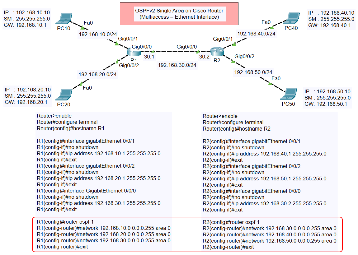
In this tutorial, we will explore how to configure OSPFv2 Single Area on a Cisco router with a multiaccess Ethernet interface. The process involves configuring interfaces and enabling OSPF on routers based on a provided topology. The setup uses two routers (R1 and R2) and multiple PCs connected in different subnets.
Dynamic Routing – OSPFv2 (IPv4)
- Configure OSPFv2 Single Area on Cisco Router (Multiaccess – Ethernet Interface)
- Configure OSPFv2 Single Area on Cisco Router (Point to Point – Serial Interface)
Topology Overview

The topology consists of the following components:
- R1 connected to:
- Subnet: 192.168.10.0/24 (PC10)
- Subnet: 192.168.20.0/24 (PC20)
- Subnet: 192.168.30.0/24 (shared link to R2)
- R2 connected to:
- Subnet: 192.168.40.0/24 (PC40)
- Subnet: 192.168.50.0/24 (PC50)
- Subnet: 192.168.30.0/24 (shared link to R1)
Each subnet is configured on GigabitEthernet or FastEthernet interfaces.
Router Configuration
Below are the step-by-step configurations for both routers:
Router R1 Configuration
- Set the hostname:
- Configure Interfaces:
- GigabitEthernet 0/0/1 (Connected to PC10):
- GigabitEthernet 0/0/2 (Connected to PC20):
- GigabitEthernet 0/0/0 (Connected to R2):
- Enable OSPFv2:
Router R2 Configuration
- Set the hostname:
- Configure Interfaces:
- GigabitEthernet 0/0/1 (Connected to PC40):
- GigabitEthernet 0/0/2 (Connected to PC50):
- GigabitEthernet 0/0/0 (Connected to R1):
- Enable OSPFv2:
Verification
After completing the configurations, you can verify the OSPF settings and connectivity:
- Check OSPF neighbors:
- Check OSPF routing table:
- Ping between PCs across routers:
- From PC10 (192.168.10.10), ping PC50 (192.168.50.10):
- From PC20 (192.168.20.10), ping PC40 (192.168.40.10):
Conclusion
This configuration ensures that OSPFv2 is operational in a single area across multiaccess Ethernet interfaces. This setup allows for dynamic routing and efficient network communication between subnets.