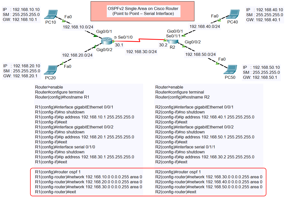
Configure OSPFv2 Single Area on Cisco Router (Point to Point – Serial Interface)
When working with Cisco routers in networking, configuring OSPFv2 (Open Shortest Path First version 2) in a single area is a common and important skill. This tutorial walks you through setting up OSPFv2 for a simple point-to-point serial interface topology.
Dynamic Routing – OSPFv2 (IPv4)
- Configure OSPFv2 Single Area on Cisco Router (Multiaccess – Ethernet Interface)
- Configure OSPFv2 Single Area on Cisco Router (Point to Point – Serial Interface)
Topology Overview

The topology consists of two routers (R1 and R2) connected via a serial interface (S0/1/0 on R1 and S0/1/1 on R2). Each router also has two Ethernet networks connecting to PCs:
- Router R1:
- Ethernet Network 1: 192.168.10.0/24
- Ethernet Network 2: 192.168.20.0/24
- Serial Network: 192.168.30.0/30
- Router R2:
- Ethernet Network 1: 192.168.40.0/24
- Ethernet Network 2: 192.168.50.0/24
- Serial Network: 192.168.30.0/30
The PCs in each network are assigned static IP addresses for communication.
Objective
The goal is to configure OSPFv2 in a single area (area 0) so that all networks connected to the routers can communicate with one another.
Configuration Steps
Step 1: Configure Router R1
- Assign Hostname:
- Configure Gigabit Ethernet Interfaces:
- Configure Serial Interface:
- Enable OSPFv2 and Advertise Networks:
Step 2: Configure Router R2
- Assign Hostname:
- Configure Gigabit Ethernet Interfaces:
- Configure Serial Interface:
- Enable OSPFv2 and Advertise Networks:
Verification
After completing the configurations, verify the OSPF neighbor relationship and routing table.
- Check OSPF Neighbors: On both routers, use the following command:
- Verify the Routing Table: Check the routes learned via OSPF:
- Test Connectivity: Use the
pingcommand from any PC to verify connectivity with devices in other networks.
Conclusion
By following this tutorial, you have successfully configured OSPFv2 in a single area for a Cisco router network with a point-to-point serial interface. This setup ensures dynamic routing and seamless communication between all connected networks.